contact us

contact us
If you would like to leave us a comment please go to
Contact Us

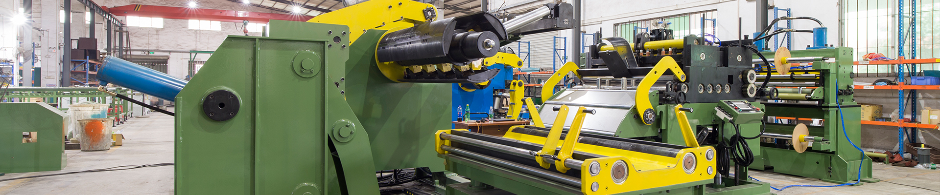
This automatic swing shear cut to length line was used to cut trapezoidal, rectangle, square, parallelogram etc. shape metal plates from coils and automatically staking in laminations. It’s widely used in stamping auto parts area, metal electrical appliances parts etc. It has advantages of cost saving, high efficiency etc. comparing to produce by punching machine and laser cutting line etc. The whole line was controlled by PLC and operated in the operation panel of the electric cabinet, it can achieve automation of the whole process such strip payoff from coil and straightening, feeding, cut to length, conveyor and auto stacking in laminations etc.
Main components of the cut to length line
1) One set of 1700 model 3 in 1 uncoiler straightener feeder with loading car.
2) One set of swing shear.
3) One set of lifting conveyor belt.
4) One set of double station type auto stacking system.
Coil was loaded, lifted and installed on decoiler’s mandrel by the auto loading car, then decoiler payoff strips and insert strip head into straightener feeder part, electric adjust straightener gap device to adjust straightening performance automatically then feed strips to swing shear after processed by straightener feeder part. Next, swing shear cut strips to required trapezoidal shape, next, the blanks were carried out by the conveyor belt and come to auto stacking system. Moreover, it set pit between decoiler and straightener feeder, so it can reserve enough loop for strip feeding part, especially for big size blank cutting.
Brief introduction of each part of the whole line
Loading car:
Function instruction: be used for moving coil to spindle of uncoiler smoothly, while uncoiling and entry the material head into straightener, it is used for supporting material head to let it entry into straightening roller smoothly, loading car is equipped with backup plate to prevent coil slipping off from loading car while moving little big distance, while hanging coil.
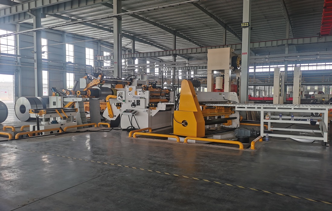
Straightener-Feeder part
Function instruction: use unbending principle to release material bending stress to straighten plate, then feed into press equipment according to set length and speed.
Bend arm device. Strip head was assisted by support arm and then press down by press arm device, then motorized rollers feed strip forwards to go through straightener feeder part.
Driven method: AC servo motor+ speed reducer.
Electric adjust straightening roller gap. Driven by 2set of servo motor/hydraulic motor to adjust straightener roller gap (refer to above image), just need to set data in HMI’s touch screen. Moreover, it has the function of memory and call it back of the producing data: such as different products different part code, straightener gap set data. It also can memory and call it back of data such as feeding length, feed speed, part code etc.
Straightening-feeding roller combination: straightening roller; assistant roller; feeding roller. Straightening roller: 9pcs (upper5pcs/down4pcs)
Backup roller device (Assistant roller): 4 columns at upper and down, making the straightening rollers have enough intensity to flat thickness and high tensile material and ensure straightening accuracy (refer to the following image).
Straightening measure display method: dial display.
Coil end detect device. It equips with sensor device, when it detects there is no strip when strip used up, power press can stop and feed also stop, then operator can operate the feeder in manual model to finish the rest stamping work.
Roller material: GCr15. All straightening rollers, feeding rollers adopt high quality of GCr15 and finished tempering & quenching,
Roller driven method: gear driving, all gears adopt tempering, carburization, high frequency quenching, precise grinding gear IT6 level precise standard.
Feeding precise: 0-1000mm, ±0.15mm/m(mould with pin can reach 0.05mm); above 1000mm, ±0.20mm/m.
Material’s exit support plate length: 400-1000mm (can be customized), the length usually was customized according to the buyer’s requirement.
Swing shear
It was comprised of hydraulic shear and swing steel base etc. It adopts double hydraulic cylinder type hydraulic shear, hydraulic shear was fixed on the swing steel base and it was driven by servo motor with speed reducer via gear and heavy duty gear ring device.
Cutting width capacity: 100-2000mm width,
Cutting thickness capacity: 0.5-4.5mm thickness, 2000mm, 3.0 mm
Swing angle: ±25°
Cutting accuracy: ±0.5mm
Shear blade cap adjust method: Manual adjust at guide of dialgauge.
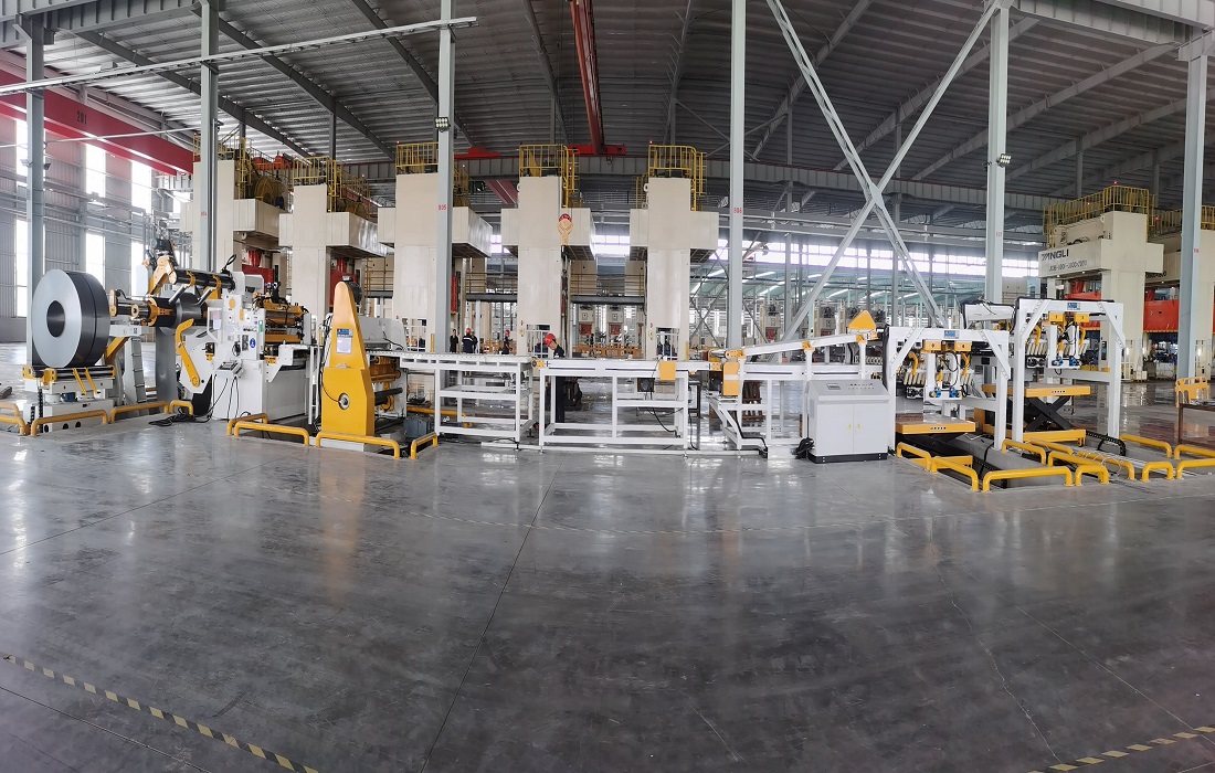
Conveyor belt and auto stacking system
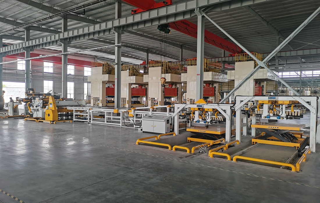
Double stations stacking system (each palletizing position has a palletizing platform)
There are 2 stacks in total, and the special-shaped blanks cut by the pendulum can be stacked by switching the conveyor belt.
Function: The plates are stacked neatly, removed by the mobile trolley and transported to the next station with a forklift. There are two mobile trolleys, which are used in turn, which greatly improves the work efficiency.
Working method: During automatic production, the palletizing trolley moves to the material receiving position, and the hydraulic lifting mechanism lifts and lowers the material. The material slides onto the stacking platform, and during the process of the material falling onto the stacking platform, the sensor triggers the sensor to control the action of the beating cylinder. The frequency of flutter cylinder can be set in the system. While staking blanks, the trolley gradually descends through the sensor console.
When the sheet count reaches the set value, the stacking trolley will descend and move out of the stacking area. After manual unloading, the trolley returns to the stacking position and starts a new round of sheet stacking. The discharge direction of the stacking trolley is the front discharge.
The movement of left and right side baffles and rear side baffles is adjusted manually, and the adjustment is in place by manual visual inspection.
Main parameters:
|
Maximum parameters: |
700mm (width)*1700mm (feeding length) |
|
Minimum piece: |
500mm (width)*300mm (feeding length) |
|
The highest stacking material: |
Max 600mm (including pallets) |
|
The heaviest stacking material: |
5000Kg (actual load 8T) |
|
Mobile trolley: |
2 sets |
|
Trolley drive mode: |
AC geared motor |
|
Lift drive: |
hydraulic cylinder |
Note: The foundation excavated for the stacking part is subject to the actual design.


